

This is the first of several articles planned for explaining cameras and their behavior in 3D applications. This article will go over some basics for what a frustum is, and how rendered objects are affected by them. I will not get into mathematics in this article, but rather concepts, to help understand “why” things happen, and what can be done about them. The next article will be more math focused.
What is a frustum?
In geometry, a frustum[1] (plural: frusta or frustums) is the portion of a solid (normally a cone or pyramid) that lies between one or two parallel planes cutting it.
Wikipedia contributors. (2020, August 9). Frustum. In Wikipedia, The Free Encyclopedia. Retrieved 03:12, October 16, 2020, from https://en.wikipedia.org/w/index.php?title=Frustum&oldid=972052480
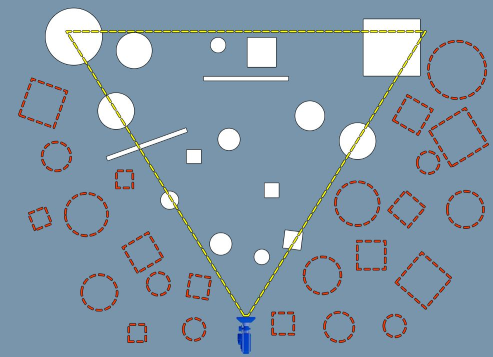
With regards to most 3D applications, a frustum is a volume representing visible space, generally a box or trapezium pyramid. With this shape, we can perform collision checks for objects within the frustum. Colliding objects can be considered visible and rendered, while the rest can be ignored. Even if we rendered the non-colliding objects, they would be off screen and the user wouldn’t be able to see them, essentially wasting resources. This type of culling is aptly named “frustum culling” and is a corner stone of any performant 3D application.
Image Source: https://docs.unrealengine.com/en-US/Engine/Rendering/VisibilityCulling/index.html
White objects are visible, dotted objects are not. Notice that intersected objects count as visible. This is to prevent objects from “popping” in and out of the scene
Orthographic vs Perspective Frustums
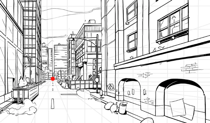
The main difference between the two is how objects are observed within the frustums. To help illustrate this, let’s look at art. Perspective lines are used to help the artist draw things with appropriate proportion, often relative to some point or horizon.
A scene drawn in single point perspective. Scene objects seem to shrink towards the point.
Image Source: https://www.howtodrawcomics.net/one-point-perspective
A model in AutoCAD orthographic layout. Here things seem paralell/orthogonal.
Image Source: https://www.youtube.com/watch?v=sg4W_Fovfyg
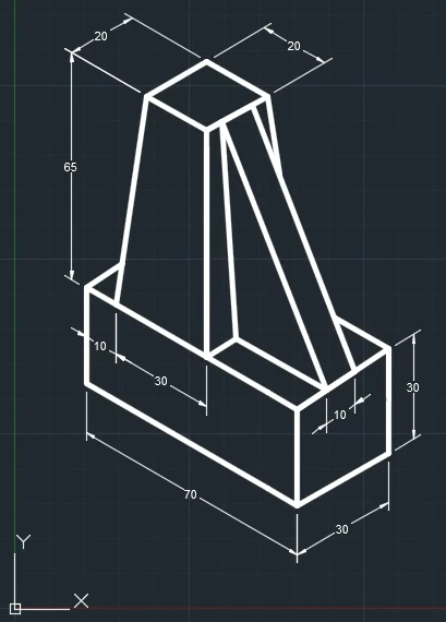
If we look closely at the images above, we can notice that in the first image, objects closer to the point appear smaller than objects further from the point. In the second image we see that the parts of the model that are further from the camera, appear the same size as the parts that are closer. Using our eyes as a counter example, if we step closer to an object, it becomes bigger, and as we step away, it becomes smaller. This difference in behavior is crucial when deciding what type of projection to use in our applications.
Position vs Size
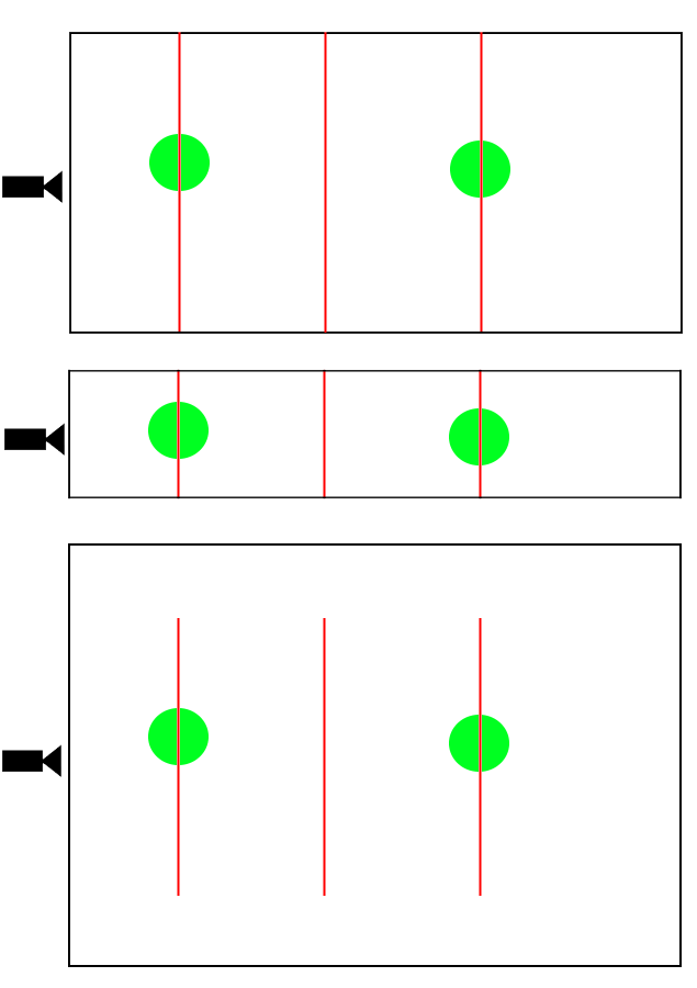
So, what is the reason for this behavior? If we draw lines through each frustum, we can see that in the orthographic case, each line is the same length, and in the perspective case, line length changes as we go further along the frustum.
black lines = frustum bounds. red lines = slice of frustum at some depth. green = object in scene as seen from camera position.
Image Source: author’s bad programmer art
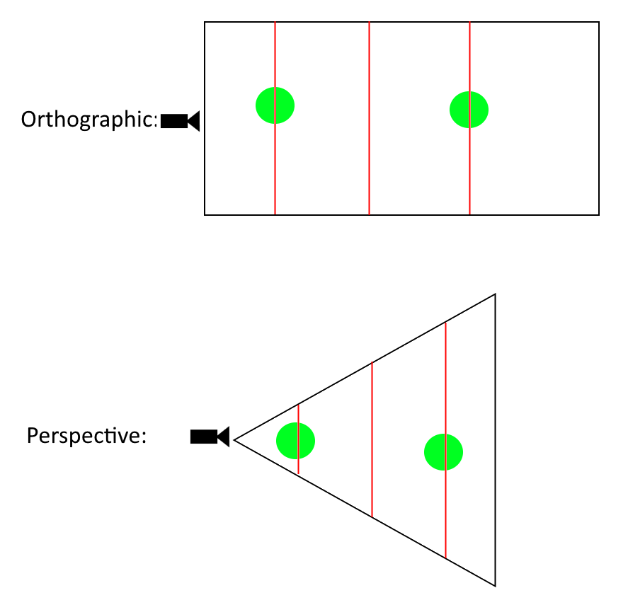
In 3D space, each line represents a plane. Looking at orthographic, we can see that each object, if drawn on any of the planes, would be the same size. In the perspective case, objects closer to the camera take up far more area than objects that are further away. This implies then, that if we change the frustum’s size and shape, we can manipulate the way objects are rendered.
Field of view, or lack thereof
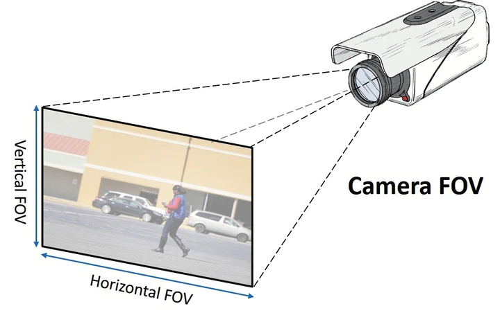
Field of view (referred to as fov from here on out) is the angle in which objects can be seen. Taking the human eye as an example, we have a vertical fov of about 135 degrees, and a horizontal fov of about 200 degrees. This means we can see more at our sides than we can above/below us. To put in simple terms, a larger fov means larger viewing angle.
If we increase horizontal fov, we would see more of the street. Increasing horizontal fov would show more of the buildings.
Image Source: https://www.securityinfowatch.com/video-surveillance/cameras/article/21081310/guidelines-for-setting-camera-field-of-view
If we go back to our sliced frustum image, we notice that this value makes sense for perspective, but the orthographic frustum is just a box! Indeed, fov doesn’t mean anything in this case, and is often omitted. To change what is visible within the frustum, we have to change the dimensions of the box itself. This is sometimes done with a “zoom” value that is multiplied to the frustum values. Let’s say I have a box that is 300 units wide. If I set a zoom value of 2, and apply it to the box, the width becomes 600, making objects appear smaller. Conversely, if I set the zoom to 0.5, the width becomes 150, making objects appear larger.
Various frustum widths show that objects will appear larger or smaller relative to the amount of space they occupy within the frustum
Image Source: more bad programmer art
Summary
Hopefully this article has given you a general understanding of the frustum and how it applies to rendering:
- Frustum culling – Objects outside the frustum are ignored, reducing rendering overhead
- Orthographic Frustum – Box shape. Uniform scale.
- Perspective Frustum – Trapezium pyramid shape. Scale changes along depth.
- FOV – Field of view. Ignored with regards to orthographic frustums, applied with regards to perspective frustums.
In the next article I will revisit these concepts in greater mathematical detail.